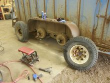

I can recall an incident driving back to the farm late one fall evening. There was something on the road ahead. I couldn’t quite make it out. On getting closer it was clear I was coming up fast on a tractor and round baler travelling in the same direction. The baler obscured the rear tractor lights and had no lights of its own. If I hadn’t been paying close attention, I could easily have run into the back of it in the dark.
The ASABE (the American Society of Agricultural and Biological Engineers) has established guidelines for lighting farm implements. In 2012 the U.S. National Highway Traffic Safety Administration adopted those recommendations, which now set the standard for lighting implements, including in this country.
Basically, the standard calls for two red taillights and signal lights on a towed implement if it blocks the tractor’s taillights. And it should have two amber flashing lights to the rear.
Read Also

John Deere introduces updated tech for its combine line
The 2027 model year will see the debut of several new features for John Deere’s line of combines, particularly the X9.
That’s a pretty basic minimum.
But most implements built before the late 1990s came without any lights. So it’s up to producers to add them. With farms getting bigger, meaning machines spend more time on the road, that has become increasingly important.
Adding lights to an older implement isn’t hard, and with low-cost LEDs available, it isn’t that expensive. The investment is well worth it.
Here’s a look at how to get some basic taillights and warning lights mounted.
Plug to play
First, if you want to connect to a newer model tractor, it likely has a standard seven-pin trailer plug. So, it’s just a matter of mounting the lights on the implement, wiring them to the appropriate pins on a connector and plugging it into the tractor. To find out which pins in a seven-pin trailer plug are associated to which circuit, just Google it. There are plenty of graphics online showing that. Then, hey, voila, implement lights.
But if you want to connect to an older tractor—one that may not even have factory warning lights—you’ll have to create a whole new lighting system from scratch.
What you’ll need
Obviously you’ll need the lights, themselves. LEDs draw much lower amperage than those with older incandescent bulbs, and they’re often brighter. That means wire gauge can be lighter, which is useful on long wiring runs — and there is less draw on the tractor’s electrical system.
Taillights and signal lights should be red, and flashers should be amber.
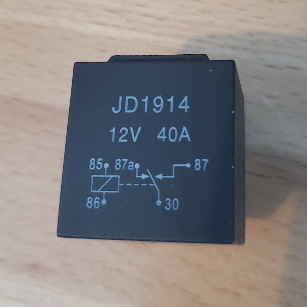
Aside from those items, you’ll need a switch, a four- or five-pin relay, and, of course, a fuse and fuse block. Signal and warning light circuits will also require a flasher unit and their own separate relays.
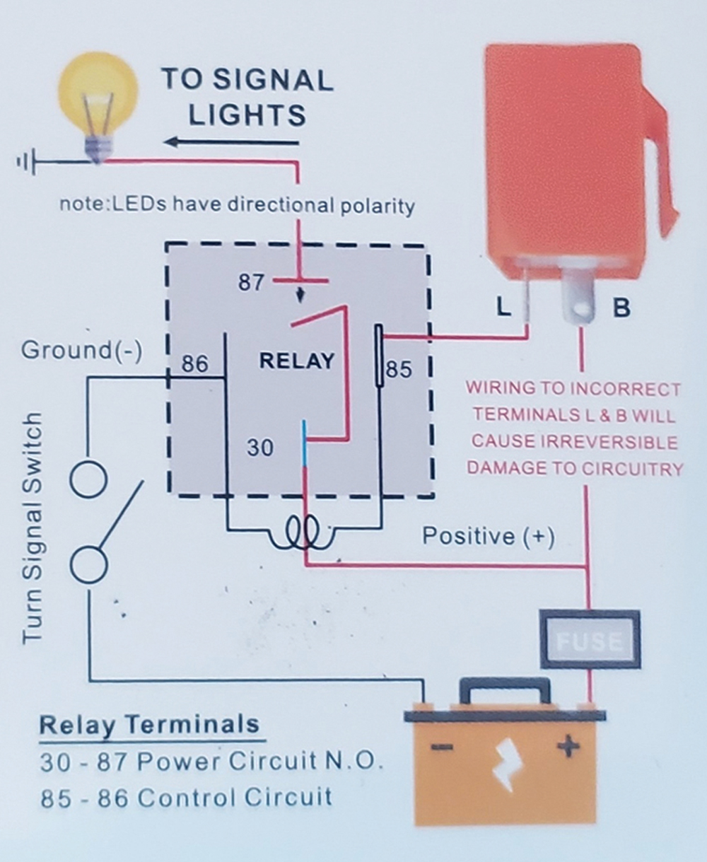
Remember, if you’re going to use LED lights, they require a special LED flasher unit. A regular one won’t work, because LEDs typically don’t draw enough amperage to activate an old-style flasher unit.
Of course, adding a trailer electrical connector to the tractor will be necessary. They are available at Princess Auto or any auto parts store.
The setup
If you’re building the circuit from scratch, put the fuse close to the battery to protect the entire wiring circuitry.
Start with a main power lead coming off the positive battery post. Be sure the gauge of wire used is heavy enough for the load, typically 18 gauge. A heavier gauge may be necessary if the distance to the lights is quite long and there are multiple lights. Length of wire run and power load are the two factors in determining wire gauge.
Run the main power circuit from the battery to the 30 post on a four- or five-pin relay. Run another circuit to a switch, then on to the relay in and out to ground through the 86 and 85 pins. When the switch circuit is closed (activated), it allows power to flow from the 30 pin through the relay and out to the lights via the 87 pin.
For regular on-or-off taillights, just run the power line from the 87 pin on the relay direct to the lights and you’re done. For flashing lights, insert a flasher unit after the switch in that circuit. As power then runs intermittently through the control circuit, current flow to the lights is momentarily interrupted by the relay.
A little fancier
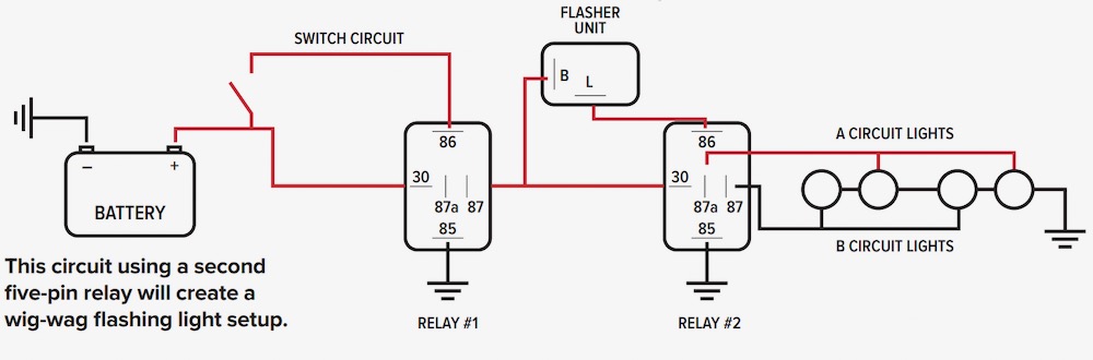
If you like a good light show, it’s possible to add a little more bling to the setup with a second five-pin relay and create a “wig-wag” effect on paired warning lights. Instead of just two lights (one on each side of the implement), a four-light setup can be created with two pairs of lights flashing alternately, kind of like what you’d see on a fire truck.
The first relay controls the circuit, turning it off and on. When it’s activated, it allows power to flow to the second relay, which distributes the current alternately to two different circuits. A second circuit from the first relay’s 87 pin runs through a flasher unit connected to the second relay’s control circuit.
On a five-pin relay, the centre pin, 87a, is a normally closed circuit, meaning it always allows power to flow unless the control circuit is activated. When the control circuit through the flasher unit closes, the second relay opens the 87a circuit and closes the 87 circuit, basically rerouting power from the 87a pin to 87.
So, connect one set of lights to the 87 pin and their paired light to the “87a” pin on the second relay. They will flash on and off alternately. A pretty simple way to create a much more effective warning light system.